Technical Data - ARC Stud Welding
ARC Studs
Mild steel threaded ARC studs are normally manufactured from low carbon mild steels in the C1010 - C1020 range. Mild steel physical properties are typically 55,000 psi minimum ultimate and 50,000 psi minimum yield. Stainless steel threaded ARC studs are normally manufactured from 18/8 stainless steels (302HQ, 304, 305). Stainless steel material properties are typically 85,000 psi minimum ultimate and 40,000 psi minimum yield. Click here for ARC stud torque strength and load strength data.
Headed Anchor studs up to 3/8" diameter are manufactured from the same material as threaded studs. Headed Anchor studs 1/2" diameter and above and Shear Connector studs are manufactured from mild steel with physical properties of 60,000 psi minimum ultimate and 50,000 psi minimum yield.
The low carbon or mild steel studs conform within reasonable limits to the analysis shown...
|
C - 0.23% max |
P - 0.040% max |
| Mn - 0.90% max |
S - 0.050% max |
Stainless steel studs materials most commonly used are types 304 or 302HQ. Other 300 series grades (except 303) are also available when required.
Threads are manufactured to class UNC-2A or UNF-2A class of fit (prior to plating) for inch sizes, and
6g class of fit for metric sizes.
Arc studs reduce in length when welded. Studs 1/2"(12mm) diameter and below will be approximately 1/8"(3mm) shorter after welding. Studs 5/8"(16mm) diameter and above will be approximately 3/16"(5mm) shorter after welding.
The base metal thickness should be at least 1/3 of the weld base diameter of the stud. This assures complete development of fastener strength, so that the weld is stronger than the stud itself. Where strength is not the foremost requirement, base metal thickness may be a minimum of 1/5 the weld base diameter.
Base Material Thickness
RECOMMENDED MINIMUM PLATE THICKNESS OF STEEL AND ALUMINUM FOR ARC STUD WELDING.
|
BASE DIAMETER OF STUD
(inch / mm) |
STEEL |
ALUMINUM |
|
Without Backup |
Without Backup |
With Backup |
|
inch / mm |
Std. Gage |
inch / mm |
inch / mm |
|
3/16 (4.8mm) |
0.036 / 0.91 |
20 |
0.125 / 3.20 |
0.125 / 3.20 |
|
1/4 (6.4mm) |
0.048 / 1.21 |
18 |
0.125 / 3.20 |
0.125 / 3.20 |
|
5/16 (7.9mm) |
0.060 / 1.52 |
16 |
0.187 / 4.70 |
0.125 / 3.20 |
|
3/8 (9.5mm) |
0.075 / 1.90 |
14 |
0.187 / 4.70 |
0.187 / 4.70 |
|
1/2 (12.7mm) |
0.120 / 3.04 |
13 |
0.250 / 6.40 |
0.187 / 4.70 |
|
5/8 (15.9mm) |
0.148 / 3.80 |
11 |
0.250 / 6.40 |
0.250 / 6.40 |
|
3/4 (19.1mm) |
0.187 / 4.70 |
*** |
*** |
*** |
|
7/8 (22.2mm) |
0.250 / 6.40 |
*** |
*** |
*** |
Accommodating the Weld Fillet
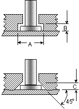
When an ARC stud is end-welded, a weld fillet forms around its base with the dimensions being closely controlled by the design of the ferrule being used. Since the diameter of the weld fillet is generally larger than the diameter of the stud, some consideration is required in the design of mating parts. Counter bore and counter sink methods are commonly used. Dimensions will vary with different stud and ferrules types. Additional methods of accommodating weld fillets include oversize clearance holes, use of a gasket material around the fillet or use of a dog-type construction.
|
STUD SIZE |
COUNTERBORE |
90° COUNTERSINK |
|
A |
B |
C |
|
inch / mm |
inch / mm |
inch / mm |
|
1/4 (6.4mm) |
0.437 / 11.1 |
0.125 / 3.2 |
0.125 / 3.2 |
|
5/16 (7.9mm) |
0.500 / 12.7 |
0.125 / 3.2 |
0.125 / 3.2 |
|
3/8 (9.5mm) |
0.593 / 15.1 |
0.125 / 3.2 |
0.125 / 3.2 |
|
1/2 (12.7mm) |
0.750 / 19.1 |
0.187 / 4.7 |
0.187 / 4.7 |
|
5/8 (15.9mm) |
0.875 / 22.2 |
0.218 / 5.5 |
0.187 / 4.7 |
|
3/4 (19.1mm) |
1.125 / 28.6 |
0.312 / 7.9 |
0.187 / 4.7 |
|
|
STUD SIZE |
COUNTERBORE |
90° COUNTERSINK |
|
A |
B |
C |
|
inch / mm |
inch / mm |
inch / mm |
|
1/4 (6.4mm) |
0.437 / 11.1 |
0.125 / 3.2 |
0.125 / 3.2 |
|
5/16 (7.9mm) |
0.500 / 12.7 |
0.125 / 3.2 |
0.125 / 3.2 |
|
3/8 (9.5mm) |
0.593 / 15.1 |
0.125 / 3.2 |
0.125 / 3.2 |
|
1/2 (12.7mm) |
0.750 / 19.1 |
0.187 / 4.7 |
0.187 / 4.7 |
|
5/8 (15.9mm) |
0.875 / 22.2 |
0.218 / 5.5 |
0.187 / 4.7 |
|
3/4 (19.1mm) |
1.125 / 28.6 |
0.312 / 7.9 |
0.187 / 4.7 | |
 |
Arc Stud Fixturing

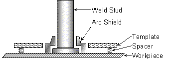
This method of templating is recommended for use with all arc shields. The template is usually a steel plate 3/32" to 3/16" thick. Spacers are required to allow gases to escape during the welding cycle. The arc shield can be held by a standard arc shield (ferrule) grip or where clearance is prohibitive a tube type set-up can be used. The recommended hole size in the template to locate the arc shields should equal the maximum outside diameter of the arc shield plus 1/32". Holes may be drilled or bored at the required stud locations. See arc shield specification sheet for arc shield details.

This method of templating is recommended for use with all stud styles. The design makes it possible to accurately hold angular alignment of the studs as well as stud location. The template should be made of ebonite or masonite and of a thickness sufficient to afford good alignment. Bushings may be used to insure greater accuracy and extend the life of the template. Standard arc shield grips are used with the tube adapter. This permits standardization of templates since it is only necessary to change the arc shield grip to weld studs of different diameters. The hole diameter of the bushing should be approximately 0.010" larger than the outside diameter of the template tube adapter.
|
STUD SIZE |
D |
L |
PART NO.
Template Tube Adaptor |
|
UP TO 1/2" |
1.25" |
2.0" |
MT-0008 |
|
5/8" - 3/4" |
1.56" |
2.5" |
MT-0012 |